The capacitor dissipation factor (DF) is one of the parameters that influence the performance of a capacitor. This parameter describes the efficiency with which a capacitor stores and releases energy. This article explores DF and its effects on the performance of a capacitor in a circuit.
What is the capacitor dissipation factor?
The capacitor dissipation factor or tangent of loss angle, often denoted as tan δ, is a measure of energy loss in a capacitor when it is subjected to an alternating current (AC) voltage. It quantifies the efficiency with which a capacitor stores and releases energy.
A low dissipation factor indicates that the capacitor is highly efficient in storing and releasing energy. Conversely, a high dissipation suggests significant energy loss and decreased efficiency. Figure 1 shows the tangent of loss angle of hypothetical ideal and real capacitors.
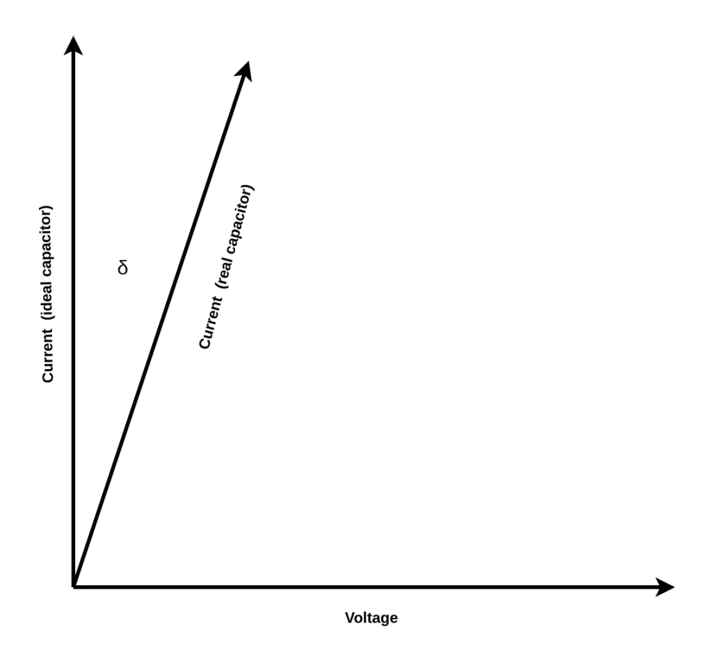
In an ideal capacitor, the dissipation factor is zero, indicating no energy loss during operation. However, in an actual capacitor, various factors such as dielectric losses and electrode resistance contribute to a non-zero dissipation factor. Additionally, imperfections in manufacturing processes can also contribute to the dissipation factor being non-zero. The dissipation factor is a dimensionless quantity, therefore it has no units.
Factors that influence capacitor dissipation factor
The dissipation factor of a capacitor is influenced by several key factors including, dielectric material, dielectric thickness, electrode thickness, frequency and temperature.
How does the dielectric material affect DF?
The type of dielectric material significantly impacts the capacitor dissipation factor, as different materials possess varying levels of inherent lossiness. Thinner dielectrics generally result in lower dissipation factors due to reduced energy loss.
Capacitors with higher dielectric constants tend to have higher dissipation factors. This is because higher dielectric constants often correspond to higher levels of dielectric loss within the material.
How do capacitor electrodes affect DF?
The electrodes of a capacitor can significantly affect its dissipation factor. Higher conductivity materials used for the electrodes tend to lead to lower dissipation factors. This is because materials with higher conductivity offer lower resistance to the flow of electric current. This results in reduced energy loss and improved efficiency in storing and releasing energy within the capacitor.
Conversely, electrodes made from materials with lower conductivity can contribute to higher dissipation factors due to increased resistance. This results in more energy loss in the form of heat.
Effects of frequency and temperature on DF
The dissipation factor of a capacitor typically increases with temperature. The rise in dissipation factor occurs due to various factors. These include changes in the dielectric properties of the material and increased conductivity of the dielectric. Moreover, alterations in the resistance of the electrodes contribute to the increase in dissipation factor.
Additionally, as temperature rises, molecular motion within the dielectric material intensifies, leading to higher dielectric losses and an increase in the dissipation factor. The heightened thermal energy can also enhance conductivity within the dielectric material, further contributing to energy loss.
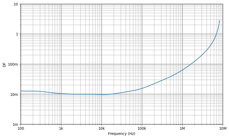
The dissipation factor of a capacitor often varies with frequency. At lower frequencies, the dissipation factor tends to remain relatively stable. However, as the frequency increases, the DF typically rises due to various factors such as dielectric losses, electrode resistance, and parasitic effects within the capacitor.
The increase in dissipation factor at higher frequencies can lead to greater energy loss and reduced efficiency in the capacitor’s operation, especially in AC applications. Figure 2 illustrates how the DF of a 1μf ceramic capacitor varies with frequency.
Relationship between dissipation factor, ESR and Q-factor
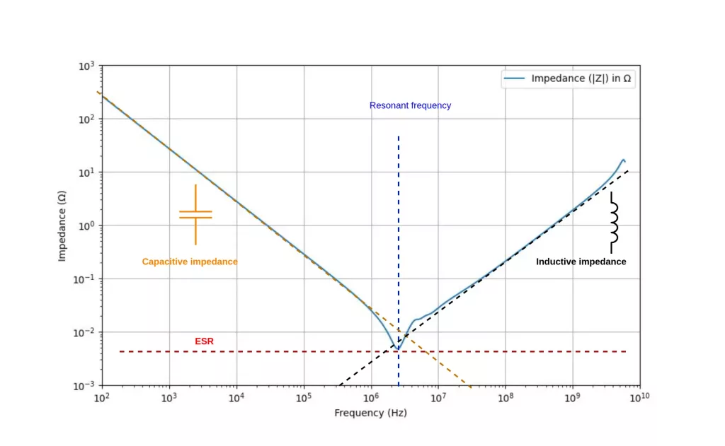
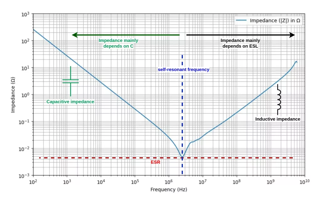
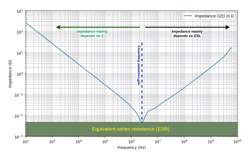
The DF of a capacitor is closely related to its equivalent series resistance (ESR). ESR represents the total resistance encountered by an alternating current (AC) as it passes through the capacitor.
A higher dissipation factor typically correlates with a higher ESR. This is because a higher dissipation factor indicates greater energy loss within the capacitor, which manifests as increased resistance to the flow of alternating current.
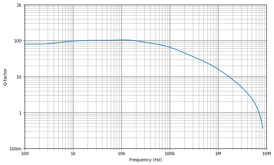
The DF and capacitor quality factor (Q-factor) are inversely related, Q-factor = 1 / tan δ. The dissipation factor represents the ratio of energy lost to energy stored in a capacitor, while the Q-factor reflects the efficiency of the capacitor in storing and releasing energy. Figure 3 shows the quality factor of a 1μf ceramic capacitor plotted against frequency.
A lower capacitor dissipation factor corresponds to a higher Q-factor, indicating improved energy storage and reduced energy loss. Conversely, a higher dissipation factor results in a lower Q-factor, indicating increased energy loss and decreased efficiency.