The impedance of a capacitor is one of the characteristics that define the behavior of a component in alternating current (AC) circuits. Determined by the frequency of the AC signal, the impedance characteristics of a capacitor influence energy storage and signal filtering. Understanding the impedance characteristics of a capacitor is essential in circuit design as it enables precise control of frequency-dependent behaviors. This article explores capacitor impedance, offering insights for engineers seeking a deeper understanding of its impact on circuit design.
What is the impedance of a capacitor?
The impedance of a capacitor is its resistance to the flow of alternating current (AC). It depends on the frequency of the AC signal: at low frequencies, capacitors have high impedance, acting like a barrier to the current, while at high frequencies, their impedance decreases, allowing more current to pass through. In simple terms, the impedance of a capacitor is how it responds to the speed of electrical signals, influencing its role in energy storage and signal filtering in electronic circuits.
Impedance characteristics of capacitor
To understand capacitor impedance, it’s crucial to examine both ideal and real-world capacitors. Ideal capacitors have pure capacitive impedance, while actual ones have additional terms including equivalent series resistance (ESR) and equivalent series inductance (ESL).
Ideal capacitor
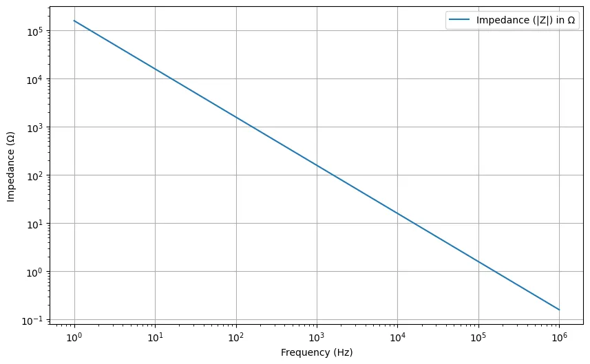
For an ideal component, the impedance is inversely proportional to the frequency of the alternating current (AC) signal. Simply put, as the frequency goes up, the impedance goes down, and vice versa. In this ideal scenario, the capacitor behaves predictably, serving as a frequency-dependent resistor that smoothly adjusts to the rhythm of the electrical signals.
The impedance of an ideal capacitor is mathematically expressed as Z = 1 / (jωC), where Z is the impedance, j is the imaginary unit, ω is the angular frequency of the AC signal, and C is the capacitance. Figure 1 illustrates the inverse relationship between the impedance and angular frequency. The equivalent circuit of an ideal capacitor is a simple capacitor symbol.
Actual capacitor
Unlike an ideal capacitor, the impedance of an actual capacitor involves additional terms. A simplified equivalent circuit of an actual capacitor (see Figure 2) contains capacitance, ESR, and ESL.

Equivalent series resistance
The equivalent series resistance of a capacitor refers to the total resistance in series with the ideal capacitance in an electronic circuit, accounting for the inherent resistance of the capacitor’s materials and construction.
Equivalent series inductance
The equivalent series inductance of an actual capacitor refers to the cumulative inductance in series with the ideal capacitance. This term accounts for the inherent inductance resulting from the physical characteristics and construction of the capacitor.
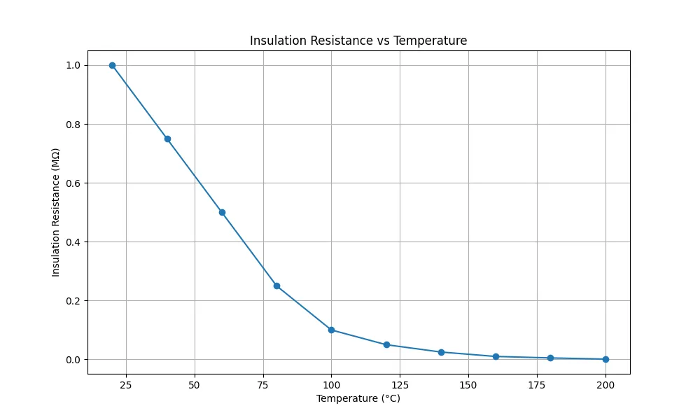
The presence of insulation between the electrodes of a capacitor introduces an additional term – the equivalent parallel resistance (EPR).
Equivalent parallel resistance
The equivalent parallel resistance denotes the presence of insulating resistance (IR) between the electrodes of a capacitor, reflecting the potential for leakage current. Figure 3 shows a simplified equivalent circuit of a capacitor with EPR.
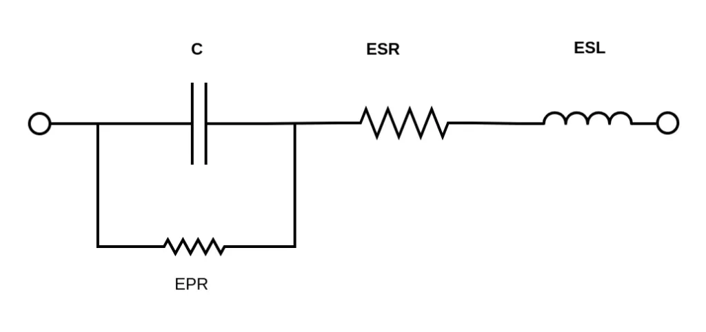
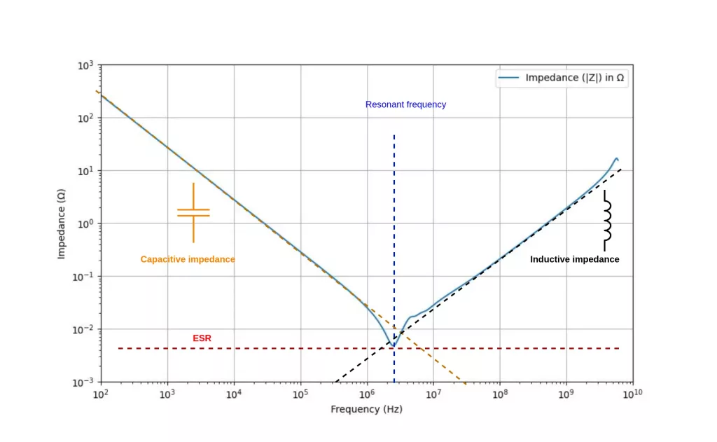
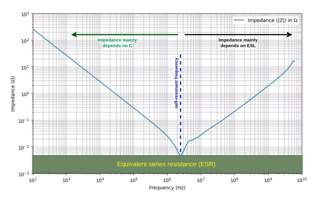
ESR and EPR contribute a resistive component to the impedance, while ESL adds a reactive component. Together, these elements—ESR, ESL, EPR and capacitance—shape the impedance of an actual component. Figure 4 illustrates the frequency characteristics of an actual capacitor.
How does impedance vary with frequency?
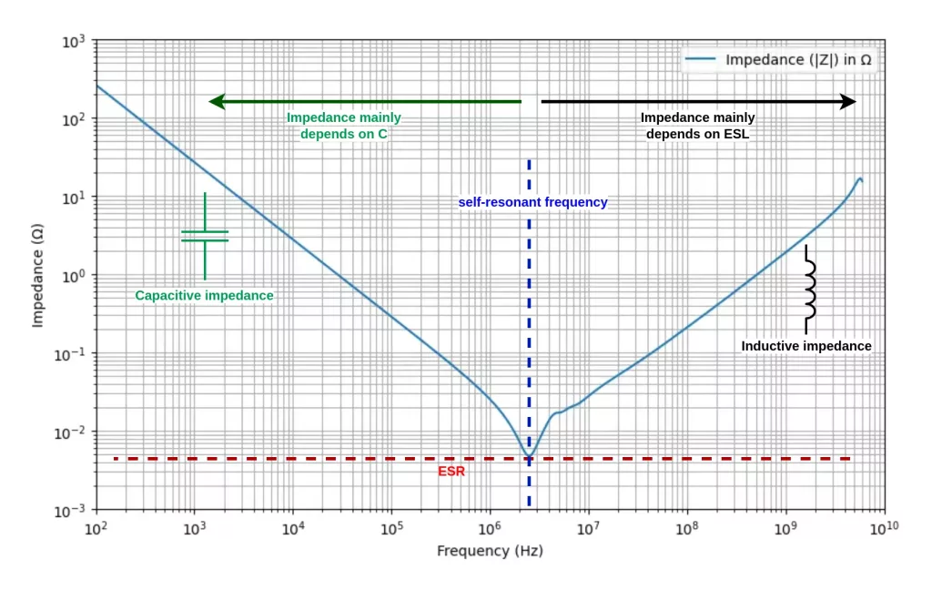
The impedance characteristics of a capacitor depict a U-shaped profile, delineating the dominance of different elements at distinct frequency ranges. In the low-frequency range, the impedance is primarily dictated by its electrostatic capacity (C). Conversely, at higher frequencies, the impedance is mainly shaped by the equivalent series inductance.
The self-resonance frequency marks the point where C and ESL resonate in series, aligning their impedances. At this frequency, the capacitive impedance is equal to the inductive impedance. Consequently, at self-resonance frequency, the ESR determines the overall impedance.
Understanding how the impedance of a capacitor behaves at different frequencies is crucial for designing circuits. It allows engineers to assess critical factors such as the noise suppression capabilities and voltage fluctuation control of a power supply line. Understanding these frequency characteristics also enables engineers to optimize circuit performance and ensure the reliability of electronic systems.

Pingback: ESL of a capacitor and its effects on impedance -
Pingback: ESR of a capacitor and its effects on impedance -